


Week One
What is a Chemical Product?
A Chemical Product is any product that is designed and/or manufactured using chemical engineering
principles.
A Chemical Product Design is the process of designing as well as developing
the chemical product itself.
One example of chemical products is under household appliances: Gas Water Heater, where gas is supplied to households. The gas is then combusted and produces fire to heat up the water.
Team Formation:
There are a total of 5 steps to have a team that has good camaraderie and is able to work well together:
-
Formation
Setting our ground rules for the team.
i. Ensuring that we are prepared for our lab sessions.
ii. Doing our fair share of the work as everything is group-based.
iii. Making sure everyone gets a chance to speak up on their ideas
iv. Helping each other out with the work.
2. Storming
Members of the team still try to work alone rather than as a group.
i. Members of the team start to open up to the others.
ii. They still prefer to work by themselves rather than working with their group mates.
iii. Instructions given by the team leader are not taken seriously and ground rules placed are
not followed.
3. Norming
Accepting one another’s differences and views. Learning to sort it out and work together.
i. Addressing the issue as a team.
ii. Discuss ways to meet the common goal.
iii. Be willing to accept and compromise.
iv. Agreeing on a solution as a team.
4. Performing
Be open and believe in one another.
i. Starting to accept each other’s views and perspectives.
ii. Every member’s perspective is as important and there are no judgements.
iii. Think about the others’ suggestions and perhaps there is a better solution, leading to a
better performance.
5. Adjourning
i. The team gets together at the end of the year to review their progress.
ii. Time is taken to recognize contributions done by each of the members.
iii. Different members of the team are given a new opportunity to take up new roles to help them
gain valuable experiences.
Reflection:
Creating a blog would help to track our progress and what we learn each week. Especially when
designing a product is not a direct or a one-step solution, and there’s definitely changes along the way.
Therefore, having a “record” of what we are doing each week would help us remember the details and
what our thought processes were like.
For example, in the past week, we got to know each other better by sharing our strengths and
weaknesses. We also hung out a lot more often than before to strengthen our bond in order to
work better as a team. After working together to complete the group activity which required us to
identify a chemical product, we learnt more about each member's thinking processes.
We managed to choose a suitable leader who will be able to consolidate all our different ideas and
lead us to manage our work better, eventually being able to work towards achieving our goals.
Documented by:
Iffah


Week TWO
Metacognition (SDL Learning Model)
-
Plan and Select
The team started to plan and brainstorm about what are some categories we want to focus on.
We applied the knowledge learnt from Year 1 and went on to research about the category we
chose (healthcare) and filter out unnecessary or irrelevant ideas that do not fit or do not have
chemical engineering principles, selecting only the appropriate resources.
2. Use
The team conducted a literature review with the chosen resources. Researching using Peer-reviewed journals, Internet search, videos et cetera.
3. Monitor
We started researching and decided to focus on people with dementia.
With scent or smell being the chemical engineering principle chosen to be incorporated into the product. However, after monitoring our progress, the team figured that this idea is not very
feasible as smell is one of the first symptoms of dementia or senses that will be lost by
dementia patients.
Hence, after realizing so, we changed our initial target audience (dementia patients) to
elderly who are forgetful and have poor hearing.
4. Evaluate
We compared our new idea with the initial idea and checked whether the chemical engineering
principle (sense of smell) still applies to the new idea. The similarity between these two ideas
was using the sense of smell, while the difference is the target audience.
Furthermore, analyzing the various resources were also required, such as what is the type of
research (peer-reviewed article, journals, books et cetera), who are the authors, when was
this research done and so forth. The team also inferred and interpreted the resources.
What we brainstorm on and our initial ideas
We decided to choose the category of healthcare products and thought of improving a medicine
dispenser in order to help dementia patients remember to take their medications as they may have
quite a number of medications to take on different timings of the day. However, we needed to find the
connection between the sense of smell and dementia and discovered that dementia patients lose their
sense of smell first. Therefore, we can no longer work with the current idea and modified our plan to
better suit the chosen chemical engineering principles. In the end, coming to a conclusion of changing
our target audience to the elderly who are forgetful and have hearing impaired.
In conclusion, for week 2, the team selected a category and target audience and researched more
during our own relative free time on some new products which we can incorporate our ideas into.
Practical 1
In the first practical, we disassembled the BD100 coffee maker and learnt about the various parts of
a coffee maker as well as their respective functions. Subsequently, we assembled it back and started
brewing the coffee and calculated the energy. Afterwards, we went back home and finished up the
report.
FIRSTLY, we drew out a schematic diagram of the coffee maker and also stated what are the operating principles of it.
Secondly, we described the bubble pump mechanism that was used in the coffee maker and explained how this mechanism was a simple, effective but at the same time inexpensive design solution to artificial gas lifting.
Thirdly, we presented the data collected from the experiment itself and explained how we measured certain measurements. For example, how did we measure the mass of one piece of filter paper accurately? To which our answer was that we took fifteen pieces of filter papers, measured the total mass of the fifteen pieces together and then proceeded to take the average of it. There were also other questions such as, "Explain how you collect and obtain the mass of the condensate", and "Explain how you get the average temperature.".
Fourthly, came the calculations. We were asked to calculate the approximate amount of energy that was transferred to the coffee in the coffee machine. We calculated this by using the mCpΔT equation. There were also some assumptions made in order for us to calculate.
For the fifth question, it was yet another calculation question, but this time for the percentage of energy consumed by BD100 that was actually transferred to the coffee. Our efficiency calculated was not very ideal as it was an extremely low percentage of around 7.39%. We thought that it might be because of the duration of the experiment being too long that led to such a poor efficiency. But of course, there are also other factors contributing to it such as, heat loss to the surrounding from the heating element, or the usage of tap water instead of distilled water, which makes it more difficult to boil.
For question six, we provided two suggestions that we thought will help with improving the percentage calculated in question five.
For question seven, we stated the assumptions made for the calculations in question four.
Last but not least, we stated a few sources of error with regards to data collection as well as calculation.
All in all, this experiment was a very fruitful experience as we get to have some hands-on activity by dismantling the coffee machine and learn about the different parts of it. We also got to have a "refresh" about some of the calculation questions.
Documented by:
Lim Xin Tong


REVERSE ENGINEERING


"Average
Temperature?"
"Obtain mass
of condensate?"


Week THREE
In this week’s lesson, we worked more on how we can improve our product such as by modifying its shape, weight and how it can be used. We learned about the concepts of SCAMPER and Feasibility Analysis Template and have implemented it with great effect.
S C A M P E R
Scamper is a tool that helps us to greatly improve and generate better ideas for our product design.
What it means:
S – Substitute
C – Combine
A – Adapt
M – Modify
P – Put to another use
E – Eliminate
R – Reverse
Feasibility Analysis Template
This is a table that helps us make sure that our product design is realistic and that the materials, equipment and manpower are available to us. It also ensures that the product design the group has come up with has to be made safe for usage while also being cost efficient at the same time. These are critical points to take note of when designing any product.
Another very important aspect that has to be noted down and carefully thought through is the project timeline. Knowing roughly how long it will take to complete the product design will help the team to better prepare for the workload. The team will have to adjust their time to suit the project so that maximum efficiency can be carried out while having equal workload between each other.
Thought process
We decided that we wanted to continue with our product design for the elderly as we find it very crucial for them to remember important things such as taking their medicine. At that age, it is highly likely that they will have a number of different medication to take and the possibility of them forgetting is very high. This could lead to troubling moments that we feel can be avoided with right chemical product given to them.
Our Ideas
Our original idea which involved a more generic product design that resembled a humidifier/diffuser. This was a very favorable idea as it is able to diffuse a large amount of scent so that the elderly person at home will be able to catch the smell even if they were in a different room.
Even though this was a good idea to us, we also had to take into account that some of the elderly might not even be at home when the smell emits which led to us coming up with product designs that they can wear/ put on their body so that they wont miss the scent.
The 2nd product design resembles a watch where they can wear it on their wrist so that it does not
get in their way too much. The other product design we came up with was if they wore it around their necks similar to how you would wear a necklace.
Product design 1 (Diffuser concept)
Product design 2 (Watch concept)
Product design 3 (Necklace concept)
Feasibility Analysis Table
COWS matrix
3 being the highest score and 1 being the lowest*
Reflection
To summarise, we have learnt a great deal more on how to pick a chemical product design. By incorporating SCAMPER and the Feasibility Analysis Template, we were able to get through this week with a lot more progress. From the COWS matrix, it is clear that the diffuser has the highest score but that does not explain the full picture. It was made clear that one of the main reasons we chose to modify our design was in the event the elderly needed to leave their homes and are separated from their diffuser. As the diffuser is not something that can be carried along, the watch and necklace concepts are still being kept in our team discussions.
The possibility for further modifications to the products are still on the table of discussion and the team will continue to brainstorm to the best of our abilities to create the most efficient product design.
Documented by:
Erik J Rozario


Week FOUR
For this week, it was an asynchronous lesson and the team had to work on what are some suitable for a baby milk bottle teat and cover. The team applied past knowledge learnt back in Year 1 Materials For Design and manage to complete the assignment. We used the COWS (Criteria, Options, Weightage, Scoring) method to select the best and most suitable material for the teat and cover of the baby milk bottle.
There were 3 steps in the material selection process:
1. Defining the material requirement for the design
2. Selecting and evaluating candidate materials (COWS)
3. Choosing the most economical materials
For the first step, we defined what was needed for a material to be suitable as a baby milk bottle teat. Such as the material has to be of low density, non-reactive with milk, have high ultimate tensile strength, and low young's modulus. We also explained why are these requirements important and needed for the material to be suitable as the material chosen for baby milk bottle teat. The same was done for the baby milk bottle cover, but with different requirements for the material.
For the second step, we used the COWS table to help us select the most suitable material for the respective parts of the baby milk bottle after the team selected a few possible ones.
For the third step, the team compared the cost and the ease of manufacturing of the different materials chosen as it is also relatively important to consider the prices of the materials.
In conclusion, this assignment has allowed the team to apply what we learnt in MFD and will help us in the future in ICPD as well.
Documented by:
Lim Xin Tong
Week FOUR

For this week, it was an asynchronous lesson and the team had to work on what are some suitable materials for a baby milk bottle teat and cover. The team applied past knowledge learnt back in Year 1 Materials For Design (MFD) and manage to complete the assignment. We used the COWS (Criteria, Options, Weightage, Scoring) method to select the best and most suitable material for the teat and cover of the baby milk bottle.
There were 3 steps in the material selection process:
1. Defining the material requirement for the design
2. Selecting and evaluating candidate materials (COWS)
3. Choosing the most economical materials
For the first step, we defined what was needed for a material to be suitable as a baby milk bottle teat. Such as the material has to be of low density, non-reactive with milk, have high ultimate tensile strength, and low young's modulus. We also explained why are these requirements important and needed for the material to be suitable as the material chosen for baby milk bottle teat. The same was done for the baby milk bottle cover, but with different requirements for the material.
Step 1: List the Material Requirements for the design
For the design of the baby bottle teat, it must be lightweight so that it is easy for the baby to hold when drinking. It must also not be reactive with the things in contact with it such as milk, and must have high ultimate tensile strength so that it is able to resist tearing and withstand stretches. Additionally, it has to be soft and elastic so that it would not hurt the baby.
For the second step, we used the COWS table to help us select the most suitable material for the respective parts of the baby milk bottle after the team selected a few possible ones.
For the third step, the team compared the cost and the ease of manufacturing of the different materials chosen as it is also relatively important to consider the prices of the materials.
In conclusion, this assignment has allowed the team to apply what we learnt in MFD and will help us in the future in ICPD as well.
Documented by:
Lim Xin Tong


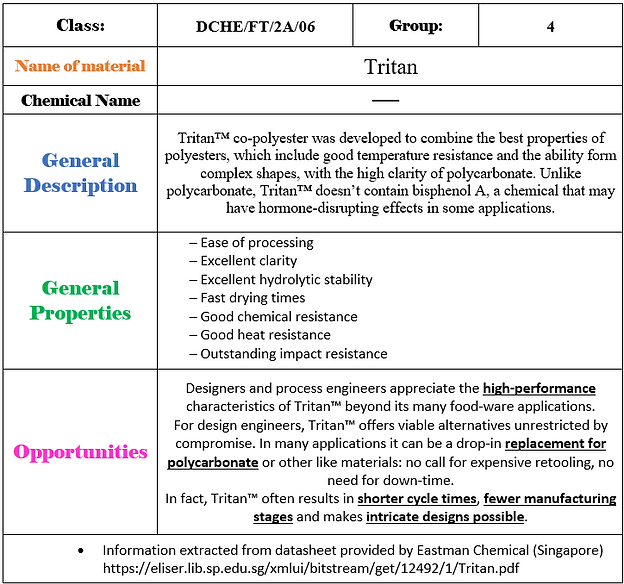
Week Five

This week we were tasked to improve on a product design by substituting its existing materials. The team decided to work on improving car windows. We decided to substitute the glass used with Tritan™ co-polyester. The team applied past knowledge of using the COWS matrix into selecting a material that allows the benefits of the product's final design to be enjoyed by the user.
Design for Materials – Worksheet for Activity
All in all, we learnt to apply this thinking process to our product design and any other assignment that requires it in the future. We have also learnt a lot from the exposure to the many different types of materials available that we were unaware of before.
Documented by:
Ofira Nascha Rosdi


Week six
In this weeks lesson, we learnt more about product design by incorporating in sustainability.
For product sustainability design, there are 2 main points:
Product Life Cycle and Cradle-to-Cradle Design.
When we design our products, we typically adopt the "materials for design" and "design for materials" mindset. However now we understand that we should also incorporate "environmental sustainability" as it is equally or if not a more important design consideration.
PRODUCT LIFE CYCLE
There are usually 6 stage in a product life cycle:
An example of Product Life Cycle of Polyethylene (Casing of Diffuser):
Example of Product Life Cycle of Acrylic (Scent container):
When we design for sustainability, it's design should be able to influence each stage of its life cycle as well as the environment. Some examples are:
- Select sustainable raw materials
- It should be able to reused, recycled or disposed
- Raw materials should be maximized to ensure zero waste
CRADLE-TO-CRADLE DESIGN
Thanks to scientists in the 1990s, this innovation is safe and has the potential of infinite use of materials in cycles.
Waste materials in an old product become the ‘food’ for a new product essentially.
Example:
Disposable stage (nutrient to nutrient)
Polyethylene can be disposed in the landfill. However, it can be reused before doing so. For example, by recycling it and selling it to other companies to manufacture into other products.
Usage stage (Solar panel)
As the product is small in size, solar panels can be used as it does not require a lot of energy to operate.
Documented by:
Erik J Rozario
MANUFACTURING
PACKAGING
EXTRACTION
distribution
use
disposal


Week sIX - Practical 2

Practical 2 – Air Lift Pump Challenge
For this hands-on activity, the roles and responsibilities of each member must be designed and listed down.
Discuss and appoint members to the following roles:
-
Team leader: Ensure all the procedures are executed
-
Experimenter: Set up and carry out the hands-on part of the experiment
-
Timekeeper: Record the time, tabulate data and plot graphs
-
Blogger: Consolidate and type the documentation in the blog (1 to 2 members)
All members are to jointly work on the discussion
A) Experimental Setup
Figure 1: Experimental Setup
The experimenter will set up the apparatus as per Figure 1 below.
For the small segment of hose, you can make one yourself (see photo instructions below)
B) Experiment Details
Experiment 1
Referring to the Figure 2 below, find a way to fix the U-shape tube to be 10cm from the base of the jug (i.e. b = 10cm). You can also ask your family members to hold the tube for you. Prepare an accurate way to measure the volume of water for the determination of the flowrate.
Adjust the length of the tubing inside the U-shape tube. Such that a is 2cm. Slide the hose segment (refer to Figure 1) up or down so that the PVC tube does not dislodge from the U-shape tube and does not have any kink.
Figure 2 Positioning of the tube
Turn on air pump and determine the pump flowrate rate. Repeat the test 3 times and average the timing. Repeat the experiment with different values of a from 2 to 10 cm. Tabulate your findings using the worksheet enclosed.
Experiment 2
Referring to Figure 2 again, with a fixed at 2 cm, adjust b to 12 cm. Measure the pump flowrate. Repeat the experiment with different values of b from 12 to 20 cm. Tabulate your findings using the worksheet enclosed.
For the experiment, have someone to video record a segment of the experiment. The video should capture the laptop screen with members with camera switched on MS Teams. The picture below explains the requirement better.
C) Experiment Worksheet
Experiment 1
Experiment 2
Questions & Tasks
-
Plot tube length X versus pump flowrate. (X is the distance from the surface of the water to the tip of the air outlet tube). Draw at least one conclusion from the graph.
Graph 1: Tube length X vs Pump Flowrate
As seen from the graph above, it can be seen that as tube length X increases, the average pump flowrate increases too.
From the process and results of Experiment 1, we can see that when a (which is the length of the tubing inside the U-shaped tube) increases, average flowrate decreases.
This means that the relationship between tube length X and pump flowrate is directly proportional, while the relationship between the length of a and pump flowrate is inversely proportional.
2. Plot tube length Y versus pump flowrate. (Y is the distance from the surface of the water to the tip of the
U-shape tube that is submerged in water). Draw at least one conclusion from the graph.
Graph 2: Tube length Y vs Pump Flowrate
As seen from the graph above, it can be seen that as tube length Y increases, the average pump flowrate increases gradually. Unlike the graph of “Tube length X vs Pump Flowrate”, which has a direct relationship with each other and the graph can be seen to be increasing quite linearly. From this graph, the average pump flowrate is increasing when tube length Y is increasing as well, but not linearly. Instead, there is a slight curve at the beginning.
From the process and results of Experiment 2, we can see that when b (which is the length between the base of the jug and the tip of the U-shaped tube submerged in water) increases, the average flowrate decreases.
This means that the relationship between tube length Y and the pump flowrate is directly proportional, while the relationship between the length of b and the pump flowrate is inversely proportional.
3. Summarise the learning, observations and reflection in about 150 to 200 words.
We learnt that the air-lift pump utilizes air to displace water. The pumped air lifts the water by entering through the bottom of the pipe and mixing with the fluid. Density of the mixture now changes. Water has a higher density than air hence, when mixed, its density will be lower than that of water. When the changes in density occur, it will cause the combined air-water mixture to rise up through the pipe.
The efficiency of an air-lift pump depends on two factors:
-
Submerged length in relation to height of air outlet.
-
Total volume of water in the jug. When conducting the experiments, there were times when we did not pour the water collected back into the jug, resulting in inaccurate results. We confirmed this after we obtained all results and observed the relationship. Additionally, we redid those few times again.
From experiment 1, when length of b is constant at 10cm, we observed that as length of a increases, length of X and average flow rate decreases as well.
From experiment 2, when length of a is constant at 2cm, we observed that as length of b increases, length of Y and average flow rate decreases as well.
4. Explain how you measure the volume of water accurately for the determination of the flowrate?
To accurately measure the volume of water, we collected the water discharged from the U-shape tube into a basin. Each run is conducted for one minute (60 seconds). The total discharged water from the basin is poured into a measuring cup to obtain an accurate volume of the water collected. This data will give us the amount of volume per minute, ml/min. With the data, we can easily convert it to volume per second by dividing ml/min by 60s. This will then give us the flowrate in ml/s.
5. How is the liquid flowrate of an air-lift pump related to the air flowrate? Explain your reasoning.
As air flowrate increases, water flowrate will also increase up to a point, after which the water flow rate levels off or may even decrease with a further increase in air flowrate. This is because an air lift pump pumps air that will be used to carry and raise the liquid up. Thus, as air flowrate increases, more air is able to carry more water up the tube, faster. However, as air flowrate increases to a point where the maximum water flowrate is equal to the maximum air flowrate the tube can carry (due to its size) water flowrates will then level off. However, if air flowrate further increases beyond this point, the amount of water that the air can carry will start to reduce as a trade off. This will then result in the further decrease of water flowrate, with that increase in air flowrate.
6. Do you think pump cavitation can happen in an air-lift pump? Explain.
No, pump cavitation cannot happen in an air-lift pump. Cavitation only occurs in the presence of liquids. Changes in pressure inside the pump turn the liquid into vapour and as the pump’s impellers spin, the vapour goes back to liquid again. The air bubbles move and pressure is increased and this results in the air bubbles instantaneously implode. In an air-lift pump, liquids are not introduced into the pump. This means that only air is inside the pump, meaning that the difference in pressure will not cause the formation of bubbles which would lead to cavitation.
7. What is the flow regime that is most suitable for lifting water in an air-lift pump? Explain.
The flow regime that is most suitable for lifting water in an air-lift pump is turbulent flow regime. The air-lift pump is a device that is used to lift water from the jug with the use of compressed air. Essentially, the water will enter from one end of the tube, and a mixture of air and water will exit from the other. In the air-lift pump, compressed air will be mixed with water. As water gets mixed with compressed air, the density of water will decrease. This is because the density of water is much higher than the density of air. By buoyancy, air will rise quickly. The main theory of air-lift pumps is the difference in density.
Therefore, to be able to lift water more efficiently in an air-lift pump, there needs to be a bigger density difference between the density of water and the density of the compressed air and water mixture. Hence, to be able to achieve that, there needs to be more mixture of compressed air and water. Thus a turbulent flow regime is needed, to have rapid variation of pressure and the velocity of the flow. In a turbulent flow, the fluid no longer travels in layers and will mix efficiently. Consequently, achieving what we want.
8. What is one assumption about the water level that has to be made? Explain.
One assumption is that the water level in the jug must be constant throughout. A differing water level in the jug would yield different flow rates even with the same parameters. This was observed after carrying out the same runs with different water levels in the jug, where our flow rate decreased as our water level decreased. However, we did redo the runs where the water levels were not the same as the others, in order to achieve accurate results.
Our video
References:
Grundfos. n.d. [online] Available at: https://www.grundfos.com/sg/learn/research-and-insights/airlift-pump [Accessed 26 May 2021].
Mechanical Walkins. 2020. Air Lift Pump - Working Principle, Parts and Working. [online] Available at: http://www.mechanicalwalkins.com/air-lift-pump-working-principle-parts-and-working/#:~:text=In%20air%20lift%20pump%2C%20the,same%20direction%20as%20the%20air. [Accessed 26 May 2021].
PI Process Instrumentation. 2017. Understanding and avoiding pump cavitation. [online] Available at: https://www.piprocessinstrumentation.com/pumps-motors-drives/article/15563623/understanding-and-avoiding-pumpcavitation#:~:text=Cavitation%20occurs%20when%20air%20bubbles,spin%2C%20back%20to%20liquid%20again. [Accessed 26 May 2021].
Vapour Tech. n.d. [online] Available at: https://www.vapourtec.com/flow-chemistry/laminar-turbulent/ [Accessed 26 May 2021].
Documented by:
Ofira Nascha Rosdi


Week seven


During this week lesson, we started learning about Computer-Aided Drafting and Design (CADD)!
More about CADD: It is the use of software where we use to draw and design physical components or to layout processes whereby in this case, we were introduced to Fusion 360 for our lesson plan.
First activity
As an introduction of the software to us, we had a simple pre-lesson activity where we had to design a keychain.
Here are some of the keychain that we have designed with the tutorial that was given to us.
In Week 12, we then received our own keychains from our lecturer which was made by using a 3D printer.
Second Activity
Following after our first activity of designing our own keychain, we had a demonstration by Mr Ting on what we were supposed to design. During this section, we were introduced to a few new icons in the software. For instance, we were introduced to coincident, tangent, mirror, concentric, trim and extrude icon in order for us to design something that looks like a door handle. This design was much more complex as compared to the first activity since there were more details we needed to do.
Here is what we did:
Overall, it was such a fun and engaging to me as I learnt more about CADD and it was the first time I learnt more about designing through a software.
Documented by:
Iffah Nadhirah


Week eight

This week, we learnt more about digital fabrication, more precisely, 3D printing. Digital fabrication enables one to quickly make anything one needs, whenever. It is also fully customisable to individual needs. Nowadays, digital fabrication is fast becoming an important enabling technology in many chemical engineering fields.
For example, it can be used in prototyping or even to replace and improve certain items. In one instance, a house was built with digital fabrication! This shows how remarkable 3D printing is.
Objective:
Our main focus today is to adopt the peer-teaching model. Our group was tasked with the following topic:
Research:
Slicer is a
-
Program that turns 3D model file (eg: STL) into a G-code script
-
Specify settings that dictate how your model will be printed
-
Important as every 3D printer is different
1. Infill density:
Measure of how much material will be printed inside the outer shell of the object in percentage.
To obtain the fastest printing, 0% infill density is preferred. This is because the product will be hollow, which reduces the time needed as compared to when has to be filled, eg. at 100% infill density.
2. Layer Height
Establishes the height of each layer of filament in the print.
Thicker layer height is established for faster printing. This is because lesser layers are needed to get the same height, compared to when a thinner layer is used.
3. Shell Thickness:
The number of layers the outer wall will have before infill printing begins.
A low wall thickness will result in faster time taken for printing. This is because it has lesser to print as compared to a model with high wall thickness.
4. Print Speed
How fast the print head travels.
The faster the print speed, the faster the time taken.
5. Support
Structures that hold up overhanging features. Reducing the need for structures will decrease printing time.
Additional findings:
While researching, my team and I have come across that using these splicer settings to speed up printing time, may also lead to certain setbacks and tradeoffs. Some of which include unstable and weak models, as well as rougher surfaces.
Conclusion:
A takeaway we got from this week's session is the importance of choosing the right splicer settings to produce works of the best quality, efficiently.
Documented by:
Ofira Nascha Rosdi
GROUP 4
FDM design requirements 2 – Slicer Setting for Fast Printing
Introduce and discuss briefly how slicer setting such as layer height, print speed, part orientation, infill density, supports and etc. can affect the time required for 3D printing.
Introduce important 3D printing terminologies such as infill density and pattern, layer height, etc


Week eight - Practical 3
PART ONE
This week, we had our third practical session. Before that we had to do our research on CARDBOARD !
PRE-EXPERIMENT
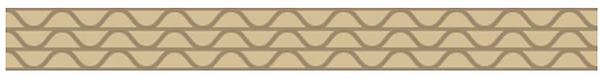
From our research, we learned that a standard sheet of corrugated cardboard is made from 3 components.
1) Sheet of corrugated or “fluted” material in the center.
2) Outer liner of paper.
3) Inner liner of paper.
Each side of the fluted material is glued to the inner and outer liner of paper during manufacture, giving it it's rigidity and stability to the papers. An example of this:
There are 2 main types of paper that are generally used for the liners: KRAFT and TEST
KRAFT:
Strongest type of paper and also the easiest to print on. Most commonly used outside liner when selecting material to produce corrugated boxes and packaging. An example of Kraft paper:
TEST LINERS:
Double layered/ duplex paper. Being recycled, Test paper is not as strong as Kraft or easy to print on.
It is commonly used for the inside liner. It is also cheaper than Kraft paper.
An example of Test paper:
Paper weights and GSM:
Once we know what type of material we will be using, knowing its weight is the next important task.
GSM = Grams per square meter
Some common paperweights used for corrugated material are: 115/125 GSM and 140/150 GSM.
Wall types:
When extra rigidity and strength is needed for making suitable packaging for heavier items, extra layers of fluting section can be added. This also provides additional protection for items that are more delicate/ expensive.
An example of a normal piece of corrugated cardboard:
When a single layer is added to the carboard, it is now known as "single wall".
An example of a "single wall" board:
When transporting particularly heavy/ large items, a "triple walled" grade can be used. This can be made when another layer of fluting and liner is added.
An example of "triple walled" board:
EXPERIMENT
For this practical, it was our first time in the FabLab.
We were introduced to the different types of joinery by our lecturers. We were educated on the differences of each kind of joinery and how they can be implemented on the cardboard. However for this practical, we focused mainly on SIX JOINERY:
For this practical session, we were tasked in recreating these six joineries by ourselves, however the team decided that we would take this practical one step further and try our best to improve each of the joineries.
After much brainstorming, we started working on the different joineries with a shared goal in mind. This ultimately led to new interesting designs that were based off the original joints.
They would now appear more interesting while also maintaining the same techniques taught to us by our lecturers for the base of the design.
As we will be conducting the practical using equipment such as penknives and hot glue guns, we were taught the proper handling techniques so as to keep ourselves safe at all times !
Wear our work gloves and always pay full attention on what you are doing.
Busy at work !
Finished products !!
The team presenting our joineries to the class:
At the end of the practical we were given a task of building a flying unicorn/ Pegasus at home.
What was given to us was a piece of cardboard with the different parts of the unicorn cut out. We would have to separate these pieces and construct the unicorn. The end task would be to find a way to make its wings move.
Documented by:
Erik J Rozario
TABS
SLOTS
SCORE + bEND
TABS + SLOTS
GUSSET
FLANGES


SAFETY
PRECAUTION


PART TWO

Assembled Unicorn:
Moving mechanism concept:


Finished unicorn:


Slots, Score + Bend used.


Week thirteen
Week thirteen was a pretty chill and fun week!
For this week, we focused on Operating Principles and Mechanism Designs.
Almost everything (such as devices, apparatus and equipment) are designed based on various working principles. These working principles could be either mechanical, electrical, chemical and also magnetism.
Before starting on the activity, Mr Ting first started us off by asking each group to think about what is the principle behind our own chemical product. For example, for our group, we thought that the principle behind our chemical product was diffusion at first, but Mr Ting soon corrected us afterwards, stating that the principle is in fact mass transfer / mass balance.
Thus, after knowing clearly what is the principle behind our chemical product, we would know that it is necessary of us to first figure out and research more about mass transfer and mass balance before actually moving on onto the stage of product design.
Following which, with the view to having mass transfer and mass balance occurring in a well-organized and competent way, mechanical movements are often needed.
The word "Mechanism" also have different meanings in chemistry and engineering.
In chemistry, mechanism is defined as the sequence of steps by which reactants are converted into products.
However, in engineering, mechanism is a device that transforms input forces and movement into a desired set of output forces and movement.
ACTIVITY TIME !!!
Finally, after understanding what is the working principle of our product and what is mechanism, we got to do our activity!
The activity for this week was for us to design a Ping Pong Ball Launcher!
We were to design a Ping Pong Ball Launcher that is able to shoot and reload ping pong ball on its own.
Some requirements stated are:
-
The device should be able to hold up to 5 ping pong balls.
-
The device should propel or shoot out the ping pong ball with sufficient stored energy.
-
The mechanism incorporated can be fully automatic, semi automatic or fully manual. (This requirement here is completely up to the groups to decide on our own, it is not restricted.)
-
Last but not least, we were to include sketches, short notes, as well as a clear description of both the propulsion and restoring mechanisms. (Which we included all in a single PowerPoint slide and presented to the class.)
Now, before we simply start designing or coming up with the different designs or ideas of how we want our Ping Pong Ball Launcher to look like or function, we have to first think about what is our mechanism that helps to project the ping pong ball out?
As well as how the ping pong balls can be reloaded independently (that means without manual help by the user) after the user shoots the first ball out already.
These 2 questions were the most important as it is the conditions stated in the "question" or "challenge" provided for us.
So, how and what did we do?
First, we thought about what mechanism we want to make use of, and came to a conclusion that we are going to use elastic potential energy to shoot out the ping pong ball.
Initially, we were at a lost as we were stuck on what kind of design would utilize this mechanism well and we were also trying to think about how to incorporate in a reloading mechanism (after getting the propelling mechanism).
Suddenly, we got the idea of utilizing the design of a "bow and arrow". The Ping Pong Ball Launcher would be shaped, in general, like a bow. However, instead of an arrow, we are now replacing it with a launch pad and ping pong ball.
How does it function then?
"BOW":
There is a shape of a bow. For the top part of the "bow", we are making use of the empty spaces above to store our ping pong balls. In this case, we are able to store up to 5 ping pong balls. For the bottom part of the "bow", it is used as a handle, for the user to hold onto.
"ARROW":
Next, is the "arrow" part. Which we converted it into a tube-like shape. Within this tube, is a launching pad, the ping pong ball that is ready to be launched or propelled out, as well as a rubber flap.
The end of the launching pad is also attached to a string, which the user can pull and release. When the string is being pulled back, the launch pad will also get pulled back accordingly. When released, the launch pad will be pushed forward and hence, pushing the ping pong ball out.
The rubber flap is there to prevent the ping pong ball from dropping out, even when the user is holding on to the bow vertically facing downwards. However, it is a flexible rubble flap, hence when the launch pad pushes the ping pong ball out, it is not strong enough to "block" or prevent the ping pong ball from shooting out.
This Ping Pong Ball Launcher is composed of a Propulsion Principle and a Ball Loading Mechanism.
Propulsion Principle: The launcher uses elastic potential energy to propel the ping pong ball.
Ball Loading Mechanism: By gravity, as one ball is shot out, the next ball will just drop down due to gravity and will be ready for the next shot.
Here is a picture of the slide we prepared and also our sketches:
With that, I conclude Week Thirteen's blog! Overall, it was a very fun and interesting lesson.
Preparation for practical 4
Let me give you a little, tiny preview of what we did over this weekend! In preparation for Practical 4, which will take place in the upcoming week!
We came to a conclusion that we were going to make a Pinball Machine!
We met up over the weekend and tried to make it, just to see what are the difficult parts when making it so that when it comes to the day itself we can be more efficient and everyone would know what to do.
We bought boards that are very similar to cardboards as we were unable to get cardboards and worked with them. It was definitely not very easy as there were specific measurements (i.e. various lengths and angles) required for specific parts of the Pinball Machine. But since there were no time constraints, as it was just a prototype of ours, we took our time to make, discuss and make necessary changes along the way. It was very fun and we felt good afterwards too as we had a finalized idea of what we want to make in order to get the Primary 3 students liking and votes (HAHAHA).
I shall not reveal too much and leave the rest to the blog for Practical 4.
See you next time! Bye bye!
Documented By:
Lim Xin Tong

Week FOURTEEN
SKETCHES AND SPECIFICATIONS
We started this week's lesson with some product sketches.
Our teacher educated us on the importance of sketches and drawings as a key technique for creative expression in product design. Most significantly, sketches or drawings enhance the understanding and provide clues for future product refinements and revisions.
For our sketches, we were tasked to sketch lines, curves, circles, and ellipses as a warm-up before moving on to sketching one-point and two-point perspective sketches.
Here are some examples of what we were tasked to sketch:
The idea was to try and draw a perfect circle as best as we can and a straight line as best as we can without any help from tools such as rulers.
ONE POINT PERSPECTIVE SKETCHES
We then proceeded to learn about one point sketches and how they are drawn.
It is essentially drawing features to a single vanishing point, which is commonly directly opposite the viewer's eye and on the horizon line. All lines parallel to the viewer's line of sight fade to the horizon in the direction of this vanishing point.
Our instructions were to try an sketch some for a milk carton, here are some of our efforts:
TWO POINT PERSPECTIVE SKETCHES
And lastly, our 2 point perspective drawing.
Two-point perspective is defined by two vanishing points that indicate two convergence points and an infinite distance away. We were tasked to sketch a 2 point perspective of a book, here is one of our sketches:
Design Specification
It is a set of documented requirements to be satisfied by a material, design, product, or service.
It is a common preliminary part of any engineering design and product development process.
Design specifications provide product design teams with the information they need to build out new features or functionality of a product.
Good design specifications allow product designers to answer the following questions:
• What are we building?
• What should the final build achieve?
• How do we measure success?
Type of Specifications relevant to product Design
Material Specification
Physical (dimension, weight, voltage required etc
Functional/Performance Specifications
e.g. Acceleration from 0 to 100 km/h in 8 sec, 50m Water resistance
Standard Specification
e.g. API 650 for weld tank for oil storage; waterproof IP67
Test Standard
e.g. ASTM E18-20 Standard Test Methods for Rockwell Hardness of Metallic Materials
After some brainstorming, the team came to the conclusion that this will be our design specification table for our chemical product which is the necklace diffuser:
At the end of the lesson, we learnt of the importance of sketches and design specifications, we will be using these skills learnt and applying it to our final chemical product design so that we can make more improvements.
Documented by:
Erik J Rozario


Week 14 - Practical 4
Here comes Practical 4!
For Practical 4, we had to make something out of cardboard, which was decided collectively that it would be a Pinball Machine! Considering the fact that a BIG part of our audience are Primary School students, we decided to go make a toy, and thus coming to a conclusion of the Pinball Machine.
As mentioned in the "Preparation For Practical 4" under Week 13's blog, we met up during the weekend to plan and measure out the required measurements such as what are the lengths, the shapes required et cetera.
We bought cardboards and brought a few other necessary equipment and items such as cutters (pen-knifes), double-sided tapes, scissors, permanent markers et cetera. Following which, we started to make the Pinball Machine already.
During the making, we also tried to think of ways to incorporate the 6 different joinery we learnt during Practical 3.
Recap!!!
The 6 joinerY
We did not use all 6 joinery but manage to use a few of them, mostly of Score and Bend.
Now, moving on to the aCtUaL day where we had to make it.
We were given around 2 hours to make the entire product, including the housekeeping at the end. It was relatively tough and challenging because due to the number of cases increasing at that point in time, we were not allowed to sit as a group on 1 table and had to be separated into pairs instead. This was a sudden change that we had to adapt to. During the previous meetup, it had already been obvious to us that it was already tough enough with all 4 of us doing it together, not to mention doing in pairs now. It was even more demanding.
We were racing against time!!!
Nonetheless, we split the team into pairs.
2 of us (Xin Tong (me) and Erik) will be focusing on the details of the Pinball Machine, and the other 2 (Nascha and Iffah) will be focusing on the base of the game as well as combining everything together since they have the base with them.
Details consist of: Plunger, flippers, blockages ("windmill", "door", a ramp, some triangles)
Base consist of: Playfield base, 2 sides, 1 top
Everything was going well at the beginning and the details were quickly done and passed over to the base team. However, there were a little bit of trouble and problem occurring when trying to assemble all the pieces together. Erik and I could not be of much help due to the restriction and all of us were stressed out as time was running out too.
In the end, the base was not solid enough, the rubber bands were not secured well and there were missing parts too. Hence, the game was not held together well at all.
The Pinball Machine did not work and this entire practical was a fail.
We brought back the Pinball Machine and met up another day to fix the game.
We realized what were the problems and came up with solutions to make it up.
After a few hours, the Pinball Machine finally worked!
Here are the picture and video of the Pinball Machine:
Picture:
Video:
We were really glad that it worked out and also learnt from our mistakes during the Practical itself.
These were the Areas For Improvement:
- Inserting the rubber band at the plunger (the place where the ball is to be shot out of)
- Make the flippers longer (the 2 "egg-shaped" parts)
- Add in more cardboards below the flippers so that the ball would not drop to that area (which is out of the playfield)
- Make the "windmill-like" parts shorter
Documented By:
Lim Xin Tong
SLOTS
TABS
SLOTS & TABS
GUSSET
FLANGES
SCORE & BEND

GALLERY
PRACTICAL 1
 |  |  |  |
|---|---|---|---|
 |
PRACTICAL 2
 |  |  |
|---|
PRACTICAL 3
 |  |  |
|---|
PRACTICAL 4
 |  |  |  |
|---|---|---|---|
 |  |